fbpx

Automotive Dash Panel Production Equipment

Project Scope:

Automotive Dash Panel Production Equipment

The customer needed equipment for the cooling, routing and inspection of automotive dash panels. Cooling fixtures were needed for maintaining the specified part shape while cooling after parts were removed from the molds.  For the routing station the desire was to minimize the number of tooling stations by utilizing a robot mounted dual ended spindle that could accomplish both routing and drilling. An assembly and inspection station was required for the dash panels so that assembly steps could be presented to the operator and immediate vision inspection could verify that the required parts were installed correctly.

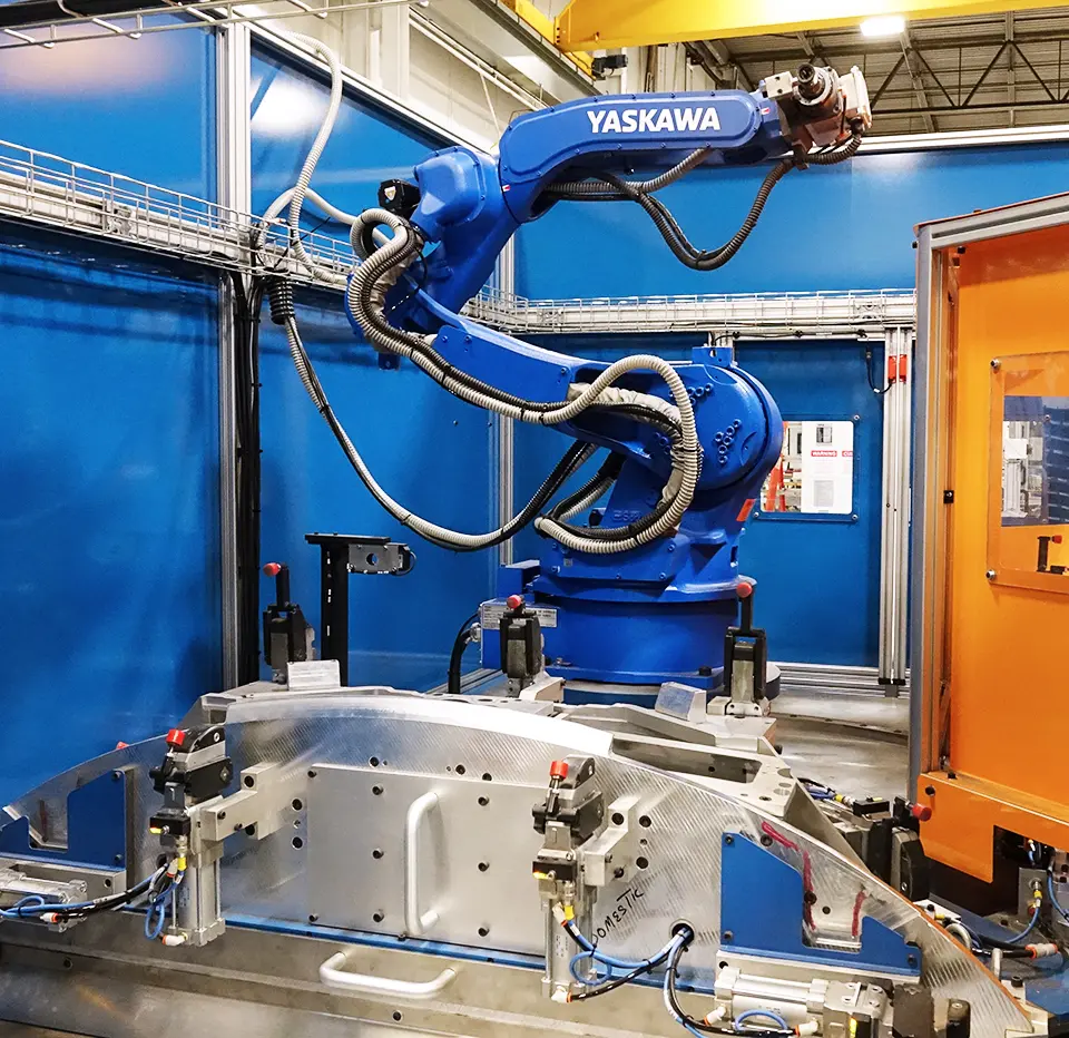
Yaskawa Motoman MH-24 Robot with DX200 Controller

Motoman Form Cut Option for routing common shapes

Motoman VFD Feedback Option for spindle motor control

Keyence Vision System with 3 cameras for Inspection Station

Rockwell Kinetix 5500 Servo for rotating fixtures from load to routing stations

Rockwell Kinetix 5500 Servos electronically geared together for part positioning at inspection station

18000 rpm spindle motor with Yaskawa vfd to control router and drill operation

Keyence color sensor for detecting black on black component

Keyence laser micrometer for measuring router bit diameter

Laser part presence detection

IR Temperature sensors for cooling process control

Rockwell Automation Panelview Plus 7 HMI’s included for machine manual control, status, and diagnostic purposes.

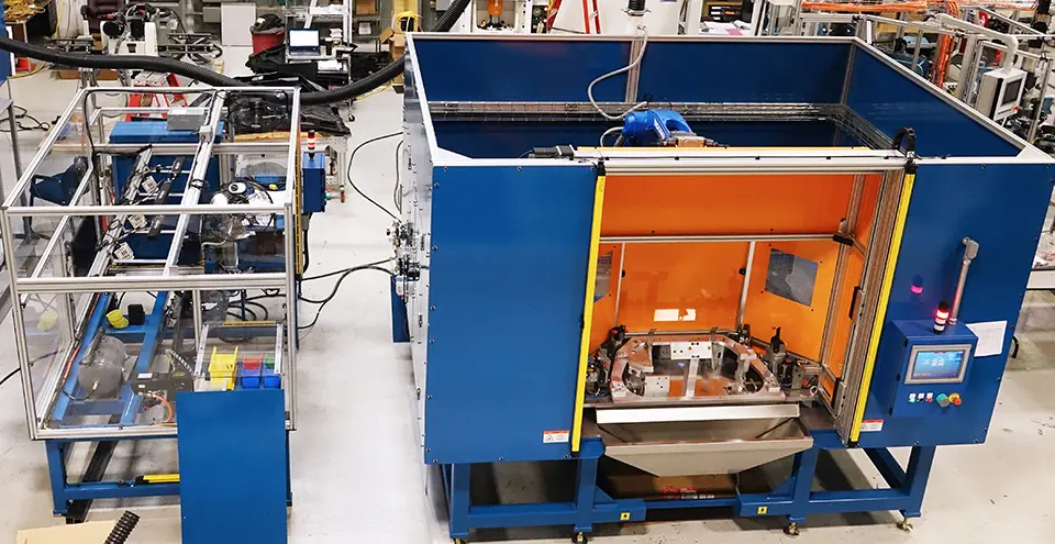
Safety Controller used to implement zone control – enabled part to be inserted at load station while robot operated on part at the routing station

Light curtains positioned at operator loading stations for ease of access while maintaining safety requirements during machine operation

I/O link enabled sensor blocks used to simplify sensor and pneumatic valve bank connection on the rotating fixture

Router bit diameter measured periodically and communicated to robot for tool wear compensation enabling holes to stay within spec with a semi-worn router bit

The Solution:

The proposed system included several manually loaded and unloaded part cooling fixtures with automated clamping and IR temperature monitoring for cooling process control. The cooling fixtures enabled the part to be cooled to a consistent shape based on strategic clamping and fixturing.

A robotic routing cell was designed with appropriate fixturing to enable the parts to have holes routed with positional and dimensional repeatability from part to part. The robotic routing station included safety system zone control to enable loading of a part while the robot was routing a part at one of two routing stations. This reduced overall cycle time and the inclusion of two routing stations enabled two different parts to be processed on one machine. Prior to shuttling a part to the routing station, the machine verified part presence using a laser sensor and verified presence of a black component attached to the part. The black on black color contrast was sufficient to be detected by the color sensor selected for the application. The routing cell also incorporated tool wear compensation based on measurement at a laser micrometer station within the routing cell. Router bits have a longer useable life when dimensional tolerances can be maintained with varying bit diameters. A dual ended spindle was incorporated so that both routing and drilling operations could be implemented without time-consuming tool changeover. The routing cell was designed so that fixtures could be interchanged at the two machine stations. Fixtures have identification allowing the machine to call the fixture specific programs without additional programming changes or setup. This functionality provided the flexibility to process multiple part types on a single machine thus reducing the capital expenditures required by the customer.

An assembly and inspection station was designed with proper fixturing, variable part positioning, and inspection for the dash assembly process. Vision inspection was included to verify after each assembly step that the required parts were installed correctly. Electronically geared Kinetix servos were used to position the part at the load, installation and inspection positions. The vision system was configured to inspect multiple part configurations. The central PLC triggered the Keyence vision system to run the required inspection sequence for the given part configuration. The control system provided real time information to the operator based on vision system inspection results.

2.5 machine rate of 1 completed part every 2.5 minutes

32 holes of varying size on each part

2 number of routing stations